This is the project page for a comprehensive suite of command line utilities for manipulating the firmware and settings of the Super Hub (VMDG480), also known as the Netgear CG3101D.
WARNING 1: CABLE MODEMS ARE OFTEN THE PROPERTY OF THE SERVICE PROVIDER. You may therefore not be permitted to disassemble or modify your modem. For experimentation, obtaining one at a reasonable price from a popular internet auction site may be preferable.
WARNING 2: CABLE MODEMS CONTAIN FACTORY CALIBRATION DATA Each modem contains unique settings and calibration data and it is not advisable to exchange the permanent settings data between modems. The calibration data within the permanent settings area has been generated in the factory using specialist equipment. Using incorrect calibration data may cause the measured and transmitted power levels to be inaccurate, and could cause the modem to interfere with other devices on the network.
Reason for Development
These utilities were developed with the primary intention of activating the built-in debugging features on the author’s modem. This was needed because the service provider was unhelpful at addressing frequent disconnects and latch-ups which were severely affecting the quality of service. It was eventually determined that an automatic firmware update had been applied which contained unstable firmware. These tools were eventually used to downgrade the modem firmware to an earlier version which didn’t exhibit the problem.
Ultimately, the service provider addressed the problem with a further firmware update. However the author no longer uses cable internet services provided by this supplier.
These utilities have been developed with the intention that they are used for Legal Academic Purposes. The utilities have been provided in source code form, and must be compiled in order to use them.
All source code is distributed under the terms of the GNU General Public Licence.
Download
The source code for the Super Hub Integration Tools is available on GitHub:
https://github.com/craigshelley/SuperHubIntegrationTools
Description of Utilities
extractmemorydump
This utility separates the individual components which comprise the firmware in the 8MB image file. These being:
- Bootloader
- Permanent Settings - Factory defaults, calibration data, certificates, per-device config eg MAC address
- Firmware Image1 - The software which runs on the router
- Firmware Image2 - A backup of the previous version of software (optional)
- Dynamic Settings - User configuration data, e.g. passwords, network configuration, system logs etc…
unpacksettings
This utility extracts the settings blocks from a 64k settings memory image obtained from extractmemorydump. It works with both dynamic and permanent settings memory images. Each time the modem writes to the settings area it will create a new settings block. If there is sufficient free space to fit the new settings block within the settings memory area, the new settings will be written without erasing the old settings. Therefore in one 64k settings memory image file, there may be more than one settings block. The modem always chooses the last (latest) valid settings block. This behaviour gives the modem the ability to survive an incomplete write e.g. power failure during write. Permanent and Dynamic settings are kept separate by storing them in different areas of the flash memory. Permanent and Dynamic settings should not be interchanged as they contain incompatible object types which the modem firmware will not understand. Dynamic settings blocks are substantially bigger than Permanent settings blocks, so much so that there is only enough room within the settings memory image to store one copy of the dynamic settings. This is a major design limitation because it removes the ability of the modem to survive an incomplete write to the Dynamic settings. As the dynamic settings contains event logs, the modem frequently updates this area of memory. Powering off the modem at the wrong time could cause the dynamic settings to be lost. Ever wondered why your SuperHub sometimes mysteriously looses its settings? The settings files generated by this tool are in the same file format as the SuperHub uses to download/upload settings via TFTP.
disassemblesettings
This utility disassembles the individual settings objects from within the settings block file obtained from unpacksettings. Each settings object describes the settings for one subsystem of the modem. The settings objects are identified by a 4 byte magic string. This enables the modem firmware to detect what type of settings object it is reading, and what class should handle it. The disassemble settings utility creates a directory containing all of the settings objects, with one file per object, and names it with a .cobj. The filename contains a number indicating the index and the magic string. The index helps to preserve the settings object order within the settings memory, though this is believed to be non-critical. The magic string helps you identify the settings object in order to make alterations. Some magic strings contain non-printable characters. Where this is the case, two character hexadecimal representation is used instead of the non-printable character.
Example:
- “CMAp” = CableModemApplication Settings
- “D0C20300” = DOCSIS 3.0 settings.
assemblesettings
This utility is the complement of disassemblesettings. The settings objects are combined together, a checksum is calculated, and the settings block saved to the specified file name. The settings block can then either be downloaded to the modem via TFTP, or packed into a settings memory image using the repacksettings utility. Take care not to mix dynamic and permanent settings objects as they are not compatible, despite sometimes having the same magic strings.
repacksettings
This utility is the complement of unpacksettings. It generates a settings memory image from The supplied list of settings blocks. As the superhub only uses the last valid settings block, this utility will, in most normal cases, be used to pack just a single settings block into a settings memory image. If however, there is a need to preserve older settings blocks, then this utility gives the option of storing multiple blocks. Note: Only the latest valid block will be used. Also note that Dynamic settings are too big to have multiple settings blocks within the settings memory image.
decompress_bootloader.sh
This shell script processes a bootloader file that was extracted using extractmemorydump. It extracts the LZMA compressed data to a .lzma file, decompresses it using the lzma utility to a .decompressed file and then attempts to disassemble the machine code using objdump to a .asm file. Beware, this shell script is not very robust, it assumes a fixed offset for the start of the LZMA data. Note: It is normal to see a warning “Unexpected end of input”
decompress_firmware.sh
This shell script takes a compressed firmware image file extracted using extractmemorydump. It extracts the LZMA compressed data to a .lzma file, decompresses it using the lzma utility to a .decompressed file and then attempts to disassemble the machine code using objdump to a .asm file. Beware, this shell script is not very robust, don’t let it eat your data! Note: It is normal to see a warning “Unexpected end of input”
spi_prog
This tool is located in the SPIProgrammer sub-directory and is used to interface with programming hardware to enable the modem’s 8MB flash memory chip to be read, written and erased. The tool also enables reading/writing to specific memory areas on the device which can be a significant time saving. The detailed documentation for this tool can be obtained from the SPIProgrammer/Readme.txt.
SPIProgrammer.hex
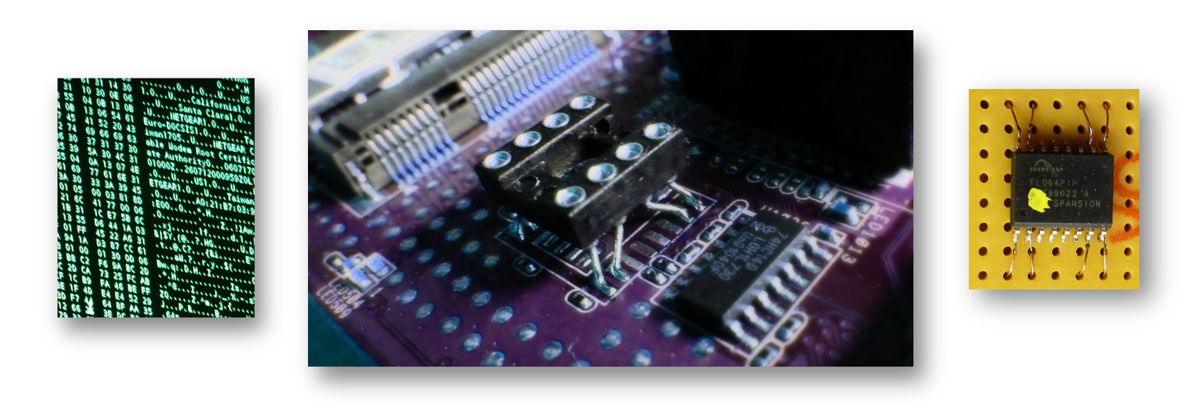
The electrical interface between the host PC and the Spansion S25FL064A 8MB flash memory chip was provided by means of USB-UART and a PIC microcontroller. After compiling the source code, SPIProgrammer.hex contains the assembled PIC firmware which communicates with the spi_prog tool, and provides an SPI interface to the target flash memory chip.
Building the Tools
Prerequisites:
- gcc
- gputils - For SPI Programmer
Build commands:
make
cd SPIProgrammer
make
If the process is successful, there will be no error messages. The compiled binaries now need to be manually copied to somewhere that is on the system path.
Usage
In this example, we will extract the firmware from a modem using the SPI programmer. The extracted firmware will be modified to enable the serial console and telnet. The modified firmware will then be writtend back using the SPI programmer utility.
(1) Read the Firmware Image from the Modem’s Flash Memory
First extract a full backup image of the whole flash memory. This takes about 12 Minutes.
Ensure you see the line Device ID 0x010216 displayed, otherwise there may be a communication
fault between the flash memory chip and the PIC.
spi_prog /dev/ttyUSB0 -r 0x000000 0x800000 my_modem.img
You should see the following output in the terminal:
Flushing buffers...
Handshake..
Query ID..
Device ID 0x010216
Reading data 0x00000000-0x00800000 (0x00800000)...
If this succeeds, you should have the following file:
my_modem.img (8388608 bytes)
Verify that the file contains data using a hex editor:
00000000   0B F0 03 21  00 00 00 00  40 08 80 01  03 E0 88 21  ...!....@......!
00000010   00 08 24 02  04 11 00 0A  00 00 00 00  01 20 A0 21  ..$.......... .!
00000020   01 40 B0 21  00 08 21 C2  04 11 00 05  00 00 00 00  .@.!..!.........
00000030   01 20 A8 21  01 40 B8 21  02 20 00 08  00 00 00 00  . .!.@.!. ......
00000040   24 09 00 40  30 8A 01 C0  00 0A 51 82  01 49 48 04  $..@0.....Q..IH.
00000050   30 8A 00 38  00 0A 50 C2  11 40 00 09  00 00 00 00  0..8..P..@......
00000060   24 0B 00 02  01 4B 50 04  30 8B 00 07  21 6B 00 01  $....KP.0...!k..
00000070   71 69 48 02  71 2A 48 02  10 00 00 03  00 00 00 00  qiH.q*H.........
If this has succeeded, then you have successfully created a backup of the whole flash memory, which can be restored to at any point in the future if things go wrong. Keep the file safe!
(2) Extract the Component Firmware Image Files from the Flash Memory Firmware Image
Extract the various firmware components using:
extractmemorydump my_modem.img
This should produce the following output (or very similar):
0x000000 - 0x0062fc Bootloader:          0x0062FC bytes > my_modem.img.bootloader
0x010000 - 0x020000 Permanent Settings:  0x010000 bytes > my_modem.img.permanent
0x7f0000 - 0x800000 Dynamic Settings:    0x010000 bytes > my_modem.img.dynamic


Image 1 Program Header:
   Signature: a0e7
     Control: 0005
   Major Rev: 0003
   Minor Rev: 0000
  Build Time: 2012/5/28 10:59:34 Z
 File Length: 3296519 bytes
Load Address: 80004000
    Filename: CG3101D_2VGUKS_V5.5.5R36_D30RG11u_20120528.bin
         HCS: 69b0
         CRC: 8cad7588
0x020000 - 0x344d63 Image 1:    0x324D63 bytes > my_modem.img.image_0x020000
You should now have the following files new files:
 my_modem.img.bootloader       (  25340 bytes)
 my_modem.img.permanent        (  65536 bytes)
 my_modem.img.image_0x020000   (3296611 bytes)
 my_modem.img.dynamic          (  65536 bytes)
The file size of the main firmware image will vary with firmware version.
(3) Extract the Dynamic Settings from the Dynamic Settings Image File
Extract the dynamic settings area using:
unpacksettings my_modem.img.dynamic
This should produce the following output:
Parameter Block Size:  0x00010000
Allocated Block Count: 0xfffffffe (1 blocks allocated)

0x00CA Settings Block 0:
  Length: 0x0000ed79
  CRC:    0x0f740199
  Checksum is valid
  Writing to file "my_modem.img.dynamic.param_00"
Here only one settings block was found because this was the dynamic settings area. You should now have the following new file:
my_modem.img.dynamic.param_00 (60793 bytes)
Disassemble the settings block using:
disassemblesettings my_modem.img.dynamic.param_00
This should produce the following output:
File:   my_modem.img.dynamic.param_00
Length: 0x0000ed79
CRC:    0x0f740199
Object: 000  Addr: 0x000008  Size:    12  Magic: CMAp     > 'my_modem.img.dynamic.param_00_settings/000_CMAp.cobj'
Object: 001  Addr: 0x000014  Size:    90  Magic: MLog     > 'my_modem.img.dynamic.param_00_settings/001_MLog.cobj'
Object: 002  Addr: 0x00006e  Size:     9  Magic: F2A1F61F > 'my_modem.img.dynamic.param_00_settings/002_F2A1F61F.cobj'
Object: 003  Addr: 0x000077  Size:   666  Magic: 8021     > 'my_modem.img.dynamic.param_00_settings/003_8021.cobj'
Object: 004  Addr: 0x000311  Size:     8  Magic: 802S     > 'my_modem.img.dynamic.param_00_settings/004_802S.cobj'
Object: 005  Addr: 0x000319  Size:    12  Magic: FACT     > 'my_modem.img.dynamic.param_00_settings/005_FACT.cobj'
Object: 006  Addr: 0x000325  Size:    43  Magic: bpi20    > 'my_modem.img.dynamic.param_00_settings/006_bpi20.cobj'
Object: 007  Addr: 0x000350  Size:    39  Magic: bpih     > 'my_modem.img.dynamic.param_00_settings/007_bpih.cobj'
Object: 008  Addr: 0x000377  Size:    28  Magic: D0C20100 > 'my_modem.img.dynamic.param_00_settings/008_D0C20100.cobj'
Object: 009  Addr: 0x000393  Size:    18  Magic: D0C20300 > 'my_modem.img.dynamic.param_00_settings/009_D0C20300.cobj'
Object: 010  Addr: 0x0003a5  Size:  1589  Magic: CMEV     > 'my_modem.img.dynamic.param_00_settings/010_CMEV.cobj'
Object: 011  Addr: 0x0009da  Size:  1060  Magic: snmp     > 'my_modem.img.dynamic.param_00_settings/011_snmp.cobj'
Object: 012  Addr: 0x000dfe  Size:     8  Magic: DnSt     > 'my_modem.img.dynamic.param_00_settings/012_DnSt.cobj'
Object: 013  Addr: 0x000e06  Size:     8  Magic: DnS1     > 'my_modem.img.dynamic.param_00_settings/013_DnS1.cobj'
Object: 014  Addr: 0x000e0e  Size:     8  Magic: UpSt     > 'my_modem.img.dynamic.param_00_settings/014_UpSt.cobj'
Object: 015  Addr: 0x000e16  Size:     8  Magic: UpS1     > 'my_modem.img.dynamic.param_00_settings/015_UpS1.cobj'
Object: 016  Addr: 0x000e1e  Size:     8  Magic: UpS2     > 'my_modem.img.dynamic.param_00_settings/016_UpS2.cobj'
Object: 017  Addr: 0x000e26  Size:     8  Magic: UpS3     > 'my_modem.img.dynamic.param_00_settings/017_UpS3.cobj'
Object: 018  Addr: 0x000e2e  Size:     8  Magic: Ppan     > 'my_modem.img.dynamic.param_00_settings/018_Ppan.cobj'
Object: 019  Addr: 0x000e36  Size:   174  Magic: RSTL     > 'my_modem.img.dynamic.param_00_settings/019_RSTL.cobj'
Object: 020  Addr: 0x000ee4  Size: 32289  Magic: Ntgr     > 'my_modem.img.dynamic.param_00_settings/020_Ntgr.cobj'
Object: 021  Addr: 0x008d05  Size:   123  Magic: PRNT     > 'my_modem.img.dynamic.param_00_settings/021_PRNT.cobj'
Object: 022  Addr: 0x008d80  Size:    55  Magic: PS0DV    > 'my_modem.img.dynamic.param_00_settings/022_PS0DV.cobj'
Object: 023  Addr: 0x008db7  Size:  1726  Magic: CAP2E    > 'my_modem.img.dynamic.param_00_settings/023_CAP2E.cobj'
Object: 024  Addr: 0x009475  Size:  1545  Magic: CDP2E    > 'my_modem.img.dynamic.param_00_settings/024_CDP2E.cobj'
Object: 025  Addr: 0x009a7e  Size:    53  Magic: CSP2E    > 'my_modem.img.dynamic.param_00_settings/025_CSP2E.cobj'
Object: 026  Addr: 0x009ab3  Size:  3179  Magic: RG2E2E   > 'my_modem.img.dynamic.param_00_settings/026_RG2E2E.cobj'
Object: 027  Addr: 0x00a71e  Size:  1806  Magic: cmp2E    > 'my_modem.img.dynamic.param_00_settings/027_cmp2E.cobj'
Object: 028  Addr: 0x00ae2c  Size:  1162  Magic: CHEV     > 'my_modem.img.dynamic.param_00_settings/028_CHEV.cobj'
Object: 029  Addr: 0x00b2b6  Size:    18  Magic: CQP2     > 'my_modem.img.dynamic.param_00_settings/029_CQP2.cobj'
Object: 030  Addr: 0x00b2c8  Size: 11267  Magic: FIRE     > 'my_modem.img.dynamic.param_00_settings/030_FIRE.cobj'
Object: 031  Addr: 0x00decb  Size:    15  Magic: VPNG     > 'my_modem.img.dynamic.param_00_settings/031_VPNG.cobj'
Object: 032  Addr: 0x00deda  Size:    30  Magic: PPPS     > 'my_modem.img.dynamic.param_00_settings/032_PPPS.cobj'
Object: 033  Addr: 0x00def8  Size:  3654  Magic: WiGu     > 'my_modem.img.dynamic.param_00_settings/033_WiGu.cobj'
Object: 034  Addr: 0x00ed3e  Size:    59  Magic: ERT2E    > 'my_modem.img.dynamic.param_00_settings/034_ERT2E.cobj'
A new directory should have been created:
my_modem.img.dynamic.param_00_settings (Directory containing 35 objects)
The number of object files will vary depending on the firmware version installed, and what previous firmware versions have been installed.
(4) Modify the Settings
We now need to make alterations to activate the serial console, to enable remote management, and to activate telnet support on the LAN side. Edit the files below in this case 020_Ntgr.cobj using a hex editor. Make the changes as indicated by the byte enclosed in square brackets in the following tables
Enable serial console: (Ntgr.cobj)
Serial Console Disabled:
0000 26A0: 00 00 FF 00 00 00 00 00  00 00 00 00 00 00 00 00  ........ ........
0000 26B0: 00 00 00 00[00]C1 C1 C1  C1 00 FF FF FF FF FF FF  ........ ........  ******
0000 26C0: FF FF FF FF FF FF FF FF  FF FF FF FF FF FF FF FF  ........ ........
Serial Console Enabled:
0000 26A0: 00 00 FF 00 00 00 00 00  00 00 00 00 00 00 00 00  ........ ........
0000 26B0: 00 00 00 00[04]C1 C1 C1  C1 00 FF FF FF FF FF FF  ........ ........  ******
0000 26C0: FF FF FF FF FF FF FF FF  FF FF FF FF FF FF FF FF  ........ ........
Enable Remote Management: (Ntgr.cobj)
See explanation below:
0000 1420: 00 00 00 00 00 00 00 00  00 00 00 00 00 00 00 00  ........ ........
0000 1430: 00 00 00 00 00 87 07[12] 17 00 00 00 50 00 00 00  ........ ....P...  *****
0000 1440: 50 00 00 1F 90 00 00 00  50 01 61 64 6D 69 6E 00  P....... P.admin.
0000 1450: 00 00 00 00 00 00 00 00  00 00 00 00 00 00 00 00  ........ ........
0000 1460: 00 00 00 00 00 00 00 00  00 63 68 61 6E 67 65 6D  ........ .changem
0000 1470: 65 00 00 00 00 00 00 00  00 00 00 00 00 00 00 00  e....... ........
0000 1480: 00 00 00 00 00 00 00 00  00 00 00 02[00]17 00 00  ........ ........  *****
0000 1490: 00 17 00 00 00 17 00 00  00 17 00 00 00 17 01 61  ........ .......a
0000 14A0: 64 6D 69 6E 00 00 00 00  00 00 00 00 00 00 00 00  dmin.... ........
0000 14B0: 00 00 00 00 00 00 00 00  00 00 00 00 00 00 63 68  ........ ......ch
0000 14C0: 61 6E 67 65 6D 65 00 00  00 00 00 00 00 00 00 00  angeme.. ........
0000 14D0: 00 00 00 00 00 00 00 00  00 00 00 00 00 00 00 00  ........ ........
0000 14E0: 02[00]17 00 00 01 BB 00  00 01 BB 00 00 01 BB 00  ........ ........  *****
0000 14F0: 00 01 BB 01 61 64 6D 69  6E 00 00 00 00 00 00 00  ....admi n.......
0000 1500: 00 00 00 00 00 00 00 00  00 00 00 00 00 00 00 00  ........ ........
0000 1510: 00 00 00 63 68 61 6E 67  65 6D 65 00 00 00 00 00  ...chang eme.....
0000 1520: 00 00 00 00 00 00 00 00  00 00 00 00 00 00 00 00  ........ ........
Change the byte indicated in accordance with the following bit mapping:
- 01 = CM Port Enabled
- 04 = WAN port enabled
- 10 = LAN port enabled
e.g. for Remote management via LAN and CM port only, use 0x01 + 0x10 = 0x11 Remote management is configured separately for three different services in the following order;
- HTTP
- TELNET
- HTTPS
Notice in the hex editor how the username/password repeat 3 times. You will need to locate the byte indicated between the * characters above, and make the appropriate change to activate remote management.
Enable Telnet: (MLog.cobj)
Telnet Disabled:
0000 0010: 73 65 72 00 04 31 32 33  34 00 03 4D 53 4F 00 08  ser..123 4..MSO..
0000 0020: 63 68 61 6E 67 65 6D 65 [00]61 64 6D 69 6E 00 00  changeme .admin..  *******
0000 0030: 00 00 00 00 00 00 00 00  00 70 61 73 73 77 6F 72  ........ .passwor
Telnet Enabled:
0000 0010: 73 65 72 00 04 31 32 33  34 00 03 4D 53 4F 00 08  ser..123 4..MSO..
0000 0020: 63 68 61 6E 67 65 6D 65 [01]61 64 6D 69 6E 00 00  changeme .admin..  *******
0000 0030: 00 00 00 00 00 00 00 00  00 70 61 73 73 77 6F 72  ........ .passwor
(5) Rebuild the Dynamic Settings Image File
Now we must reverse the data extraction procedure to reprogram the new settings.
assemblesettings my_modem.img.dynamic.param_00_settings/*.cobj my_modem.img.dynamic.param_00_modified
This should produce the following output:
Reading:   my_modem.img.dynamic.param_00_settings/000_CMAp.cobj
Reading:   my_modem.img.dynamic.param_00_settings/001_MLog.cobj
Reading:   my_modem.img.dynamic.param_00_settings/002_F2A1F61F.cobj
Reading:   my_modem.img.dynamic.param_00_settings/003_8021.cobj
Reading:   my_modem.img.dynamic.param_00_settings/004_802S.cobj
Reading:   my_modem.img.dynamic.param_00_settings/005_FACT.cobj
Reading:   my_modem.img.dynamic.param_00_settings/006_bpi20.cobj
Reading:   my_modem.img.dynamic.param_00_settings/007_bpih.cobj
Reading:   my_modem.img.dynamic.param_00_settings/008_D0C20100.cobj
Reading:   my_modem.img.dynamic.param_00_settings/009_D0C20300.cobj
Reading:   my_modem.img.dynamic.param_00_settings/010_CMEV.cobj
Reading:   my_modem.img.dynamic.param_00_settings/011_snmp.cobj
Reading:   my_modem.img.dynamic.param_00_settings/012_DnSt.cobj
Reading:   my_modem.img.dynamic.param_00_settings/013_DnS1.cobj
Reading:   my_modem.img.dynamic.param_00_settings/014_UpSt.cobj
Reading:   my_modem.img.dynamic.param_00_settings/015_UpS1.cobj
Reading:   my_modem.img.dynamic.param_00_settings/016_UpS2.cobj
Reading:   my_modem.img.dynamic.param_00_settings/017_UpS3.cobj
Reading:   my_modem.img.dynamic.param_00_settings/018_Ppan.cobj
Reading:   my_modem.img.dynamic.param_00_settings/019_RSTL.cobj
Reading:   my_modem.img.dynamic.param_00_settings/020_Ntgr.cobj
Reading:   my_modem.img.dynamic.param_00_settings/021_PRNT.cobj
Reading:   my_modem.img.dynamic.param_00_settings/022_PS0DV.cobj
Reading:   my_modem.img.dynamic.param_00_settings/023_CAP2E.cobj
Reading:   my_modem.img.dynamic.param_00_settings/024_CDP2E.cobj
Reading:   my_modem.img.dynamic.param_00_settings/025_CSP2E.cobj
Reading:   my_modem.img.dynamic.param_00_settings/026_RG2E2E.cobj
Reading:   my_modem.img.dynamic.param_00_settings/027_cmp2E.cobj
Reading:   my_modem.img.dynamic.param_00_settings/028_CHEV.cobj
Reading:   my_modem.img.dynamic.param_00_settings/029_CQP2.cobj
Reading:   my_modem.img.dynamic.param_00_settings/030_FIRE.cobj
Reading:   my_modem.img.dynamic.param_00_settings/031_VPNG.cobj
Reading:   my_modem.img.dynamic.param_00_settings/032_PPPS.cobj
Reading:   my_modem.img.dynamic.param_00_settings/033_WiGu.cobj
Reading:   my_modem.img.dynamic.param_00_settings/034_ERT2E.cobj

Length:    0x0000ed79
Checksum:  0x0f740199
Writing:   my_modem.img.dynamic.param_00_modified
Note: Your checksum will be different to the one shown above, and should be different from the original checksum. You should now have the following new file:
my_modem.img.dynamic.param_00_modified (60793 Bytes)
Note: The size may be different from shown above, but should be identical to the original file size.
Next, rebuild the dynamic settings memory image:
repacksettings my_modem.img.dynamic.param_00_modified my_modem.img.dynamic_modified
This should produce the following output:
Block 00, Opening my_modem.img.dynamic.param_00_modified
Blocksize: 0x00010000
Block 00, Bytes Read: 0x0000ed79
Writing to: my_modem.img.dynamic_modified
You should now have the following new file:
my_modem.img.dynamic_modified (65536 Bytes)
(6) Write the Dynamic Settings to the Modem’s Flash Memory
Finally, program the dynamic settings back to the flash memory:
spi_prog /dev/ttyUSB0 -w 0x7F0000 my_modem.img.dynamic_modified
This should produce the following output:
Flushing buffers...
Handshake..
Query ID..
Device ID 0x010216
Erasing 0x007f0000-0x007fffff (0x00010000)...
Writing data 0x007f0000-0x00800000 (0x00010000)...
That’s it boot up your modem, and you should have telnet and serial console access.