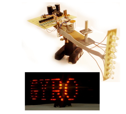
The WhirlyGIG writes scrolling messages in the air using only 8 LEDs. The LEDs sweep through the air on the end of a rotating arm and flash in sequence to produce the message display.
Introduction
This page documents a project from 1999-2000 and is now quite dated, as will be evident from the content. The world has since moved on, microcontrollers have gotten cheaper and more powerful, and electronic components are now easy for anybody to obtain. When this project was developed there was great difficulty in obtaining sufficiently bright LEDs, PCBs had to be etched at home, and most components were salvaged from scrap appliances.
This project was inspired by a publication in Practical Electronics Magazine December 1994, called ‘Space Writer Wand’. The article gave the full build instructions for a hand-held wand which would magically write messages in the air. Furthermore, the Space Writer had an incredibly simple schematic and could easily be understood by a 12 year old curious mind. The only drawback of this project was that it involved sending off by mail order to the author for a ‘pre-programmed microcontroller’, the cost of which could not be justified.
In 1998, Practical Electronics magazine published a series of articles with the title ‘EPE PIC Tutorial’. The doors to a new world of microcontroller programming were now open, and following an initial projects to build PIC based motor speed controllers for RC cars, the Space Writer project from four years earlier suddenly became viable. The first attempt at replicating the Space Writer project from 1994 yielded an unsatisfactory result for two reasons. Firstly, the mercury tilt switch which was used to detect the start of movement was notoriously unreliable at triggering consistently and a lot of practice was needed in order to achieve the correct swing of the wand. Secondly, the LEDs used were too dim, and despite being driven with more than the rated current, the lights in the room needed to be turned off in order for the messages to be visible. The WhirlyGIG was developed to overcome these problems, and produce a vivid, stable, animated display.
Numerous clocks and gadgets have since been made commercially available which write messages in the air. There will of course now be better documented projects using Arduino, which would in most cases be the preferred route for most electronics hobbyists to build their own persistence of vision display.
Overview
The WhirlyGIG is an electronic display created using only 8 LEDs and shows a scrolling text message. The LEDs sweep through the air at a relatively high speed on the end of a rotor, and flash specific patterns at precise time intervals. To the viewer, it has the appearance of a curved LED matrix sign with scrolling text. The sign has a full 360 degrees viewing angle, but there is a point at the back of the sign where new text appears, and old text disappears. The display is based on a PIC16C84 microcontroler, and the message is fully user programmable. The original program design allowed a 256 character message to be Hard-Coded into the PIC program memory. Another version of the program was produced to allow the message to be streamed via a link from a computer. The serial version of the software has no limit on message length.
Principle of Operation
When an intense light source is swept through the air, glowing trails can sometimes be seen. The effect of the air appearing to remain glowing after the light source has moved is an optical illusion. This effect relies on the ‘Persistence of Vision’ of the viewer’s retina (the photosensitive part of the eye). In general, the human eye has an exceptionally quick reaction time in detecting dark to light transients, however for light to dark transients it is much slower. This causes a temporal memory effect which can produce interesting effects especially with bright light sources in dark conditions.
The WhirlyGIG display comprises of a strip of 8 high intensity LEDs attached to the end of an arm which rotates about a central axis with a radius of approximately 20cm. The LEDs always point outwards, so they are only visible during approximately half of their cycle. As the LEDs rotate, they produce the text by changing their pattern at precise time intervals. This is controlled by the software running on a the PIC16C84 micro-controller.
Although the WhirlyGIG produces a really eye-catching display, a few assumptions have been made that are inherently part of the design. Firstly, it is important that the viewer’s eyes remain perfectly still while the display is scanning. Eye movement causes the display to be completely corrupted. This side effect is more noticeable to some people than to others. Secondly the viewer’s eyes must have the correct reaction and persistence characteristics for the LEDs to appear to write the message in the air. When showing the display at an exhibition, people in the younger age ranges appeared to be able to see the display more clearly than older people, who often said they just saw 8 flashing LEDs spinning around.
Hardware
Although a lot of time was spent designing the various components of this display, not much thought was put into how they all fit together. This approach meant there were many problems that had to be rectified as they arose. The display can be broken down into four main components, base, rotor, control PCB and LED strip.
The base component is the weighted base section from a Helping-Hand soldering work aid. This is attached via electrical screw terminal to the shaft of the drive motor. The arrangement used here is to have the drive motor inverted, so that the shaft is fixed, and the housing rotates with the rotor arm and LEDs. The motor housing is attached to the main rotor arm which consists of a strip of PCB glued to the mounting face plate of the motor. This PCB is used in conjunction with a stationary spring to commutate electrical power from the stationary base to the electronics controlling the display. The motor shaft is used as the electrical return path. The LED strip is fastened to the rotor by stiff copper wires. The control PCB and a set of counter weights are also attached to the rotor using nuts and bolts. In order for the control circuit to have a repeatable trigger point in the cycle, a photo interrupter is used to create a pulse at a specific point in every rotation. The photo-interrupter requires a stationary flag fixed to the base.
Circuit Description
The main PCB controls the power to the motor and LEDs. It receives signals from the photo interrupter and the power source. Since there is only one electrical connection that passes to the rotor (that used for power), the communications link from the computer is achieved by modulating the data onto the power supply. At the heart of this circuit is a PIC16C84 micro-controller. This is clocked using a 4.43361875MHz crystal (likely salvaged from a TV), and supplied with 5V from a voltage regulator. All LED outputs are buffered using bipolar NPN transistors. The LED strip therefore has a common anode arrangement. The motor is controlled by the PIC using a Power MOSFET.
The two large capacitors seen on the PCB are used for supply smoothing. It was anticipated that the software would take much longer to complete than creating the hardware, so programming ports were fitted to the PCB to make in-circuit programming easier and quicker. Diodes are used to isolate the incoming supply from the smoothing capacitors, allowing the power connection to be used as a communication interface. This raw supply voltage is then limited to 5V using a resistor and Zener diode, and used as a serial data input to the PIC. Ribbon cables are used to interconnect the control PCB to the LED strip.
The schematic diagram of the WhirlyGIG is relatively simple because of the micro-controller based design. The data/power modulator circuit shown on the right of the schematic diagram modulates RS232 data from a PC serial port onto the power supply of the WhirlyGig. This removes the need to use a third electrical connection for data. In order to receive the data, the PIC must be programmed with the Serial Communication version of the firmware, see the Downloads section. WARNING be extra careful when making connections to a computer. The communication circuit ASSUMES that the power supply used is completely isolated and floating with respect to that of the computer. They must NOT share a common ground/0V line. This circuit does not in any way conform to the RS232 interconnection specifications.
Power
Although it is a little unorthodox to use the motor in an inverted configuration, and have the control circuit rotating at high speed, this configuration dramatically reduces the number of electrical connections that have to be made to the spinning rotor. The current design uses the motor shaft as the ground, and +Ve pick-up on the underside of the rotor PCB. A bent radial spring, insulated from the base using a grommet, is used to commutate power primarily because it provides a low friction, low wear contact. The data modulation from the PC serial port is achieved using a power MOSFET biased to be normally on when the serial port is in its inactive state. As only an N-Channel MOSFET could be located at the time the project was being built, and a PC RS232 port is normally held at ~ -10V, a very crude inversion was achieved by transposing the ground and signal wires that come from the computer serial port. It is recommended that this part of the circuit be revisited and extra protection be added, should anybody decide to use this design.
Software
The software is by far the most complicated part of the design. Two separate programs were written for the PIC, one with a hard-coded 256 character string, and one with the ability to receive data from a computer serial port. Both programs use every byte of program memory the PIC has to offer. The software is written in PIC assembler, but sub-divided into functions that perform specific tasks. These functions are then all called from within a main loop, and from the interrupt handling routines. The program utilises two jump tables. The first contains the character string to be displayed. The second contains the font face information. The character strings are stored as ASCII values. A decode function is used to decode these values into the correct indexes for the font table. A self-test routine is used on start-up to confirm the motor and electrical pick-up are sufficiently frictionless, and that the rotor is in balance. This is achieved by measuring the acceleration and deceleration characteristics of the rotor while the power to the motor is modulated using PWM. Full power is only applied to the motor once it has has passed this self test, and the rotor has achieved a rotational speed of at least 150 RPM. If the speed of the rotor reduces below 300RPM during normal operation, the the self-test is re-run. Due to the loading on the motor bearings, they require lubrication to be applied approximately every four hours in order to achieve the correct operating speed. The serial version also has the routines to handle the serial communication. This includes buffer handling functions. On start up, the buffer is loaded with a default string Hard-Coded into program memory. Since the communication is simplex, synchronisation characters have to be introduced into the stream. These special characters ensure that the computer and WhirlyGIG are synchronised by freezing the display between message updates. The display is unfrozen when the synchronisation character has been erased from the buffer. This requires the computer to keep track of the buffer, and using a combination of accurate timing and synchronisation characters, a continuous stream of text can be achieved. Finally, there are two special characters for turning off and on the motor.
Downloads
- Schematic Diagram
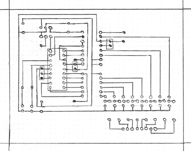
- PCB Layout
- Whirlygig.asm PIC assembly for 256 character hard-coded message
- Whirlygigs.asm PIC assembly code for serial communication
- Courier-Font.asm Courier font
- Whirlygig-sender.pl Perl script communication program
Specifications
- Display resolution: 150x8 pixels
- Rotor Speed: 320 RPM
- Message size (hard-coded version): 256 chars
- Default message size (serial version): 30 chars
- Buffer size (serial version): 48 chars
- Font Face: Courier
- Serial baud rate: 600 baud
- Supply Voltage: 7.5-12 volts
- Supply Current (operational): 400mA
- Supply Current (power save): 2mA